Friday, April 24, 2015

DC circuits

Lab Day 17: DC Circuit Analysis

Purpose: The purpose of today's lab is to look at direct circuit relationships where we use light bulbs as resistors connected to a voltage source in both series and parallel. We will analyze how to make a light bulb brighter/dimmer and specifically look at different types of resistors. 

We started by connecting a circuit in series and in parallel in order to maximize the brightness of the bulb. In order to maximize the brightness of the bulbs, we need to maximize the current delivered to the bulbs.

Professor Mason then had a setup of two different circuits that was connected to a switch. When the switch was closed the bulbs lit up. 
When the switch was closed in the second circuit displayed, the brightness of the bulbs remained the same because the potential across remains the same in the circuit.
Our predictions were correct the the upper and lower brightness remained the same.
We measured the current using the ammeter to confirm our predictions that the current is the same through the wire as seen in our circuit diagram.
Resistors
We looked at colorful resistors that were found to have different resistances with different color bands and we found that each band is used to identify the resistance using the chart given.
Here, we found the resistances of 4 different types of resistors.

The board below shows the values for the resistances of each resistor calculated from the chart based on each color band.
We then looked at resistors connected in series and in parallel. We found that in series circuit the currents are the same but the voltage divides. In parallel circuits, the voltage is the same everywhere. The current divides and the voltage remains the same, therefore the current into a node is equal to the current out of the node.
Multiple Loop Problem
Finally we explore Kirchoff''s loop and current rule where Professor Mason gave us a problem with multiple loops. The calculations used to find the current in each branch was found using the basic steps shown to find each component.
In this part we use parallel and series circuit analysis to reduce the circuit to calculate the total resistance of a complex circuit.


Sunday, April 19, 2015

Vpython: Electric Potential Ring of Charge and uniform line of charges

Purpose: The purpose of this activity is to be able to calculate the cell potential using vpython program when there are two parallel uniformly charged rods or a charged ring.

A ring of charge (in blue) was created using vpython where we placed multiple observation points on the ring itself that gave the net total potential at each point around the ring based on these 4 spheres that were designed approximately in the middle of the charged ring.


The results show that the cell potentials were V=-2.25, -2.73, -2.25, 0, 2,25, 2.73, 2.25,0 respectively 1-8 locants going around the ring from the top. The 8 observation locations were set and the results was as predicted as the cell potential changes around the ring but is the same at opposite points of the ring. The cell potential are zero when the positive and negative cancels out as seen in the model.

I created two charged rods by using multiple point charges in a straight line creating a line of charge.  Six codes of charges were added parallel to each other on each side of the observation points. The 4 observation points were then placed in between at the designed locations where the total electric potential values were calculated and displayed for each point due to the charged rods.


The electric potential energies were shown above.

Potential, Charge distributions

Lab Day 14 :4/16 Potential, Charge distributions

Purpose: The purpose is to explore the potentials on different types of charge distributions: on a ring of charge or a charged rod at a given point. The different methods of deriving the calculations of cell potential at a point will be identified and compared using excel and manual calculations.


Calculations:

Potential from a Charged Ring

We came up with the calculations of the potential from a charged ring in that we found the exact value through the integral. The integral was used where all the charges in a ring of charge q is the same distance r from point P on the ring of the axis which therefore makes r constant. The limits of integration was from 0 to 20. The value obtained was then compared to the excel calculations where we divided the ring into 20 segments which gave an approximation of the total potential.

Change in potential using E-Field
Another method we can use to calculate cell potential in the same problem is taking the integral of the E-field. In the calculations, we were able to find the E-field in the x-component as the y-component cancels out. Next, the potential was found using the integral of the Electric field in the x-component and setting the limits of integration from infinity to x.  


The equation calculated symbolically came out to be the same as the first method. 
Potential of Finite length Line Charge


Looking at a finite-length line-charge, we found the electric potential using the the given charge density and adding up all the infinitesimal point charges using the integral of potential. Therefore the potential at the desired point can be found using the symbolic solution. In fact if we wanted to find the work done to move a charge from one point to another then we can use W=QdeltaV. We can observe that the work done is independent the path along which the charge 
moves. Therefore if we move the charges, the work will not change. 


Equipotentials
The idea of an equipotential surface is that no work is done when the electric charge travels along that surface. Therefore making equipotential lines always perpendicular to the electric field lines.The potential is the same at every point of the surface. 
\
Experiment: Electric Potential Lab/Activity
In this experiment, we measured the electric potential at several points on a sheet due to a potential difference. The setup below shows a conductive paper with two point charges attached to a power supply creating a potential difference of the voltage source. We moved the voltmeter 1 cm intervals toward the right creating 10 points and also measured the in between points. The main conclusions of this activity is that the ratio of the (change in voltage and change of position) is the same as the electric field strength. The potential energy goes from high to low in the direction of the electric field as seen in our results below.


Potential vs. Position Graph of Results

Conclusion: We can calculate the potential from a charged ring using the limit of the sum as an integral and also using the integral of the Electric field as both gives the same results. We also explored the idea of a Finite line of charge where the electric potential was once again calculated and approximated using excel. The idea of equipotential surface is important for analyzing potentials on a surface as the potentials are the same at every point on the surface in which it is perpendicular to the electric field. Based on our experiment, we also found that he potential decreases toward the direction of the electric field strength.


Power and Potential

Lab Day13: 4/14 Power, Potential

Purpose: We will identify how energy dissipations work in a circuit and also look at the electrical potential energy in relationship to voltage. We will focus specifically on the work done along the electric field and the work relationship between electric potential and the electric field.

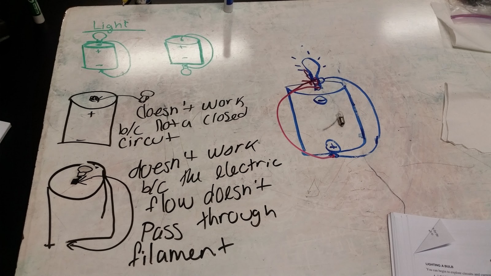
We were able to play around with light bulbs, batteries, and wires to create the dimmest and brightest light bulb circuits.
We started by trying to make the light bulb lit the dimmest and the brightest. We found that when we connected the circuit in parallel, we get the brightest while connecting it in series result in a dim light bulb. 
Water Heater experiment
The apparatus setup below is an ohmmeter used to find the resistor of the heater. Looking at the mass of water, time, and power, we can find the change in temperature. The temperature due to different voltages supplied can be observed in the graphs. Using Q=mCdeltaT,we can find the heat and energy generated by the heater. 

 
In this portion we take a look at the temperature change with a supplied voltage and it showed that there is a steady increase with voltage. Our next question was what would happen to the temperature when we double the voltage?
Supply Voltage vs. Time
The results show that the slope increases by more than double seen in the blue line. The slope went from 0.003235 to 0.02191 C/s with a voltage increase. 

Voltage vs. Time (two different voltages)
The mass of the water, power, and time is used to identify the relationship using P=IV between supplying a voltage to a water source found in the water heater experiment.

Work on Different Paths against E-field
Next, we explore work using electric fields. The work in different paths are present where one path is in the direction of the E-field, second is perpendicular, and third is at an angle. We compare these different paths and found that the path parallel does the most work, while the perpendicular path does no work at all. This is because the electric field produces a force that is in the same direction as the the path. The path present at an angle to the E-field is less as there is a x and y component. Therefore there is no work being done on the path that is perpendicular to the E-field.
The board below shows the work done in relationship to the gravitational field mgh.
Equipotential Lines
Equipotential lines are perpendicular to the electric field lines. 
The potential energy of a charge is found by taking the integral of the force. Therefore the electric field can be used with ds which is the distance along the field. The electric potential is found as the integral along the path of a to b of the electric field dot ds.
We ended class by discussing the difference between plagerism and collaboration. The difference is found in that plagerism is presenting some one else's work as your own. While collaboration is working together and actually working on it on your own. 

Vpython example: point charges and cell potential
We used vpython to find the electric potential with multiple point charges or charge distributions. We created multiple charges and multiple observation locations. The cell potential was displayed and changed as we added more point charges. If we look the board above we will see that the net electric potential is the sum of all the potentials at each charge which was calculated using the program code below.This is very useful when looking at the potential across many charges.

Conclusion: We discussed parallel and series circuits and see how we can change the orientations to get the best results as seen in the dimmest and brightest light bulb generated. We started to see that there is a relationship with power and voltage where we used the water heater problem as an example to show how P=IV. The electric potential is applied when we took derivations of the electric field. Using Vpython we can look at the electric potentials at multiple point charges showing that it is additive and can be superimposed. 

Monday, April 13, 2015

Current, Voltage, resistivity


Lab day 12: 4/9/15: Current, Voltage, Resistivity

Purpose: We look at the different relationships between current, voltage, and resistivity using light bulbs, batteries, and multimeters that allow us to find physical and qualitative meanings to each. The idea of lighting a bulb and connectivity will be analyzed.

Lighting a Light Bulb
We started off class by lighting a light bulb using a battery and a wire. This was done by closing the circuit connecting a wire from the positive terminal to the negative terminal. We were able to look at the basic usage of light bulbs, wires, and batteries. A light bulb consists of a filament that is attached to the end of a bulb which is then attached to the other side of the battery.

We went on to analyze different rearrangements of light bulbs which allows it to light up. When the light bulb filament is not directly on the bulb of the battery, the light bulb will not light up. The light bulb will also not light up when it is not in a closed circuit. This is due to the fact that the electric flow doesn't pass through the filament which is what makes the bulb lit. Therefore the way it lights up is when the bottom end of the battery is connected to the top bulb which has a filament connected to the top end of the battery creating a closed circuit. 

Making it Brighter
We found that when two batteries are put together, the light bulb becomes twice as bright. The light bulb is seen to shine brighter due to more work being done which supplies energy to the bulbs.  

Electroscope
When we supplied a positive charge to the electroscope, we observed that nothing happened. In fact the reason is because in a battery, we can see that a current is being supplied which causes electrons to flow which means work is being done on the bulb to make it lit. 
In fact an important point to be made is that a wire is needed to go back from the bulb to the battery because it allows electrons to flow in and out of the battery resulting in an equilibrium charge in which work is being done to supply the energy.


We can find  the power of this setup using P=IV and we see that a 1.5 volt battery will supply a power of 0.18 J/s .


Old Ammeter Experiment
In this experiment we are able to measure the current that flows into the battery and the current that flows out of the battery using an ammeter. We predicted that it would be the same current in and out as what goes in should be the same going out through the wires. 
The current did end up being the same as the current going out of the wire which proves that the work being done to light the bulb does not affect the current running through the wires even if energy is being used. Therefore we can restate that current does not change with the energy.

The drift velocity was calculated where it is the velocity of the flow current of electrons. The drift velocity depends on the electron charge, area, the number density, and the current.  It is found that current flows through the wire where there is a cross sectional area of the wire which can be used with the current and constant to find the drift velocity. The value we calculated has a magnitude that is small where electrons move very slow.

When we look at current and voltage relationship, we predict that it is proportional and increases linearly. The charge is also constant and proportional in a similar fashion.  The experimental results show that this is true and that there is a dependence on resistance which is the type of material used. Including resistance we get Ohm's law V=IR which explains the relationship between voltage, current, and resistance.


In this part we compare two different wires of different lengths. We found that the 200 cm longer coil has more resistance due to more material. The 160 cm long resistor is shorter which will decrease the resistance. As we measure different lengths of wires we find that the resistance is proportional to the length. As we increase the length, the resistance increases.


Conclusion: We analyzed the relationship between current, voltage, and resistivity by looking at each one separately. We also find that using batteries, wires, and light bulbs we can analyze its relationship through the work-energy supplied to light a light bulb. The current however is not affected by this and remains constant through the wire. The proportionality of current and voltage was found to be related to resistors found using Ohm's law which is not always the best way to calculate resistance. Therefore the equation based on physical properties is a better way to find the resistance of a resistor.